SBC Pinout, Cables and Interfaces
The SBC has the following interfaces:
The picture below shows the generic pinout of the SBC connectors.
Notice that each connector has a unique shape so it is physically impossible to connect the cables in the wrong place.
In case you need to prepare your own custom wiring harness here you can find the connector part numbers:
Description |
Cable connector |
SBC connector |
|---|---|---|
Analog input, digital input/output/PWM |
Molex #430251000 |
Molex #430451000 |
Power, CANbus |
Molex #430250400 |
Molex #430450400 |
Ethernet, 2 x RS232 |
Molex #430251200 |
Molex #430451200 |
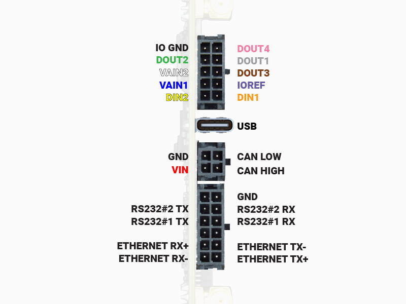
The general pinout of the SBC is shown in the picture below, where the name of the pins is colored based on the cable color.
Ethernet, RS232#1 and RS232#2 interfaces have a physical connector so the pin names are not colored on purpose.
Analog inputs
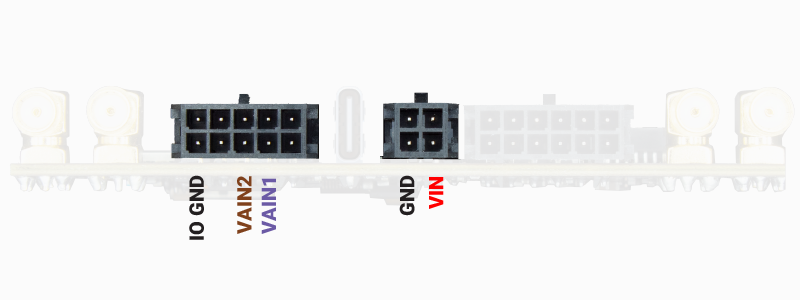
Pins which voltage can be read by the SBC.
The SBC supports two analog input pins: VAIN1, VAIN2.
In addition to these dedicated pins, you can also monitor the SBC power voltage VIN.
The resolution of the analog reading is 12-bits.
Important
Analog input voltage is between 0V and +22V
Analog input ground is connected to SBC IO GND, which is different from SBC GND. Both SBC IO GND and SBC GND can be connected together if needed.
Note
For a description and examples of the methods to read these signals, please go to the SBC Classes - AIN specific documentation.
Digital inputs
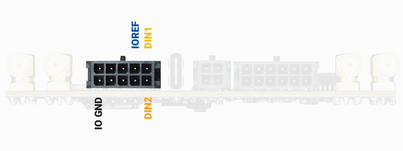
Pins which digital status (ON/OFF) can be read by the SBC.
The SBC supports two digital input pins: DIN1, DIN2.
Important
Digital input voltage is between 0V and +30V
Voltage level logic:
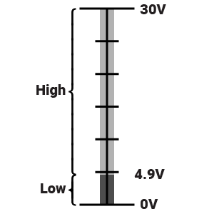
Digital input ground is connected to SBC IO GND, which is different from SBC GND. Both SBC IO GND and SBC GND can be connected together if needed.
Note
For a description and examples of the methods to read these signals, please go to the SBC Classes - DIO specific documentation.
Digital outputs (including PWM)
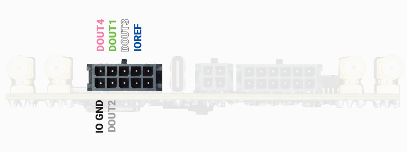
The SBC supports six digital output pins: DOUT1, DOUT2, DOUT3, DOUT4.
Each of these pins can be configured as a standard digital output (0/1) or as a PWM output.
Note
We have a specific section where you can find details and schematics of devices that you can connect to the SBC digital outputs, such as: DC motors, Servo motors, Stepper motors and Relays.
Note
For a description and examples of the methods to read these signals, please go to the SBC Classes - DIO specific documentation.
Timepulse
GPS1 Timepulse signal can be used via Digital output pin DOUT1.
In order to use it, the following code must be added:
>>> import machine
>>> ret = machine.Pin( "DOUT1", machine.Pin.IN )
USB
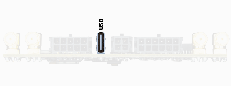
The SBC has a USB type C connector that allows you to power the SBC and connect/configure the following devices:
SBC STM32 microprocessor - microPython terminal
SBC internal flash or SBC microSD card (if inserted) EXAMPLE
GPS/GNSS receiver 1
GPS/GNSS receiver 2 (if available) EXAMPLE
GPS/GNSS receiver 3 (if available) EXAMPLE
XBEE socket 1 (if available) EXAMPLE
XBEE socket 2 (if available) EXAMPLE
4G modem (if available) EXAMPLE
Note
In the Power module section you will learn to turn on/off the different SBC peripherals.
Once turned on, they will appear as a COM port at your PC.
2 x RS232
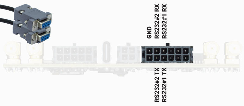
The SBC has two RS232 outputs:
RS232#1 is connected to the STM32 microprocessor and can be configured at will (maximum baudrate is 250kbps) EXAMPLE
RS232#2 is always connected to GPS/GNSS receiver 1 UART 2 port
Important
GPS2 and GPS3 should be powered on in order to use RS232#2.
Example to turn ON GPS2 and GPS3 in order to use RS232#2:>>> import sbc >>> pm = sbc.Power_Module() >>> pm.gps2and3_on()
Note
For a description and examples of the methods to read these signals, please go to the RS232 specific documentation.
Ethernet
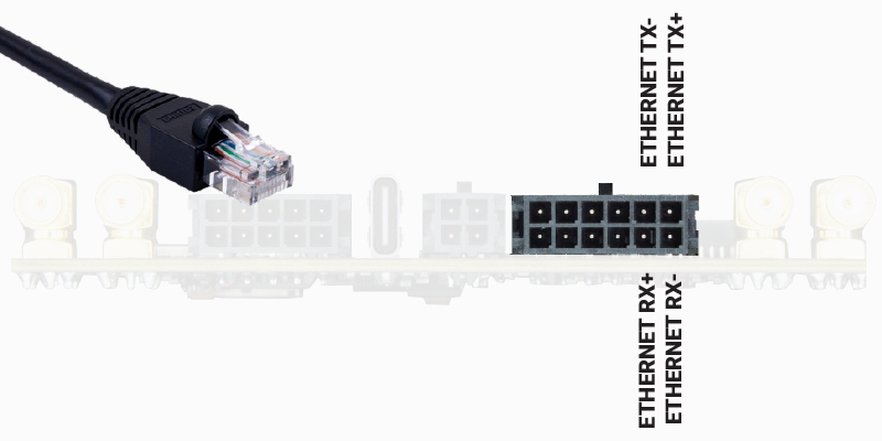
The SBC has an Ethernet connection than can be used to connect the SBC to an internal network or Internet.
Note
For examples, please go to the Ethernet example section.
CAN Bus
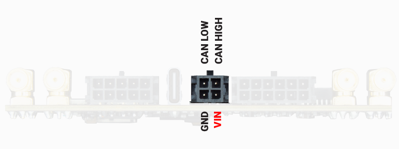
The SBC has a CAN Bus connection that can be connected at any CAN Bus network and act as a CAN Bus node.
Note
For examples, please go to the CAN Bus example section.
Important
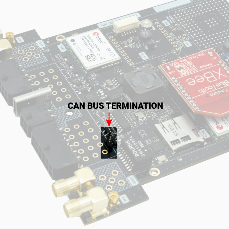
A CAN Bus network must have a terminating resistor between CAN High and CAN Low for it to work correctly.
For maximum range over long distances, the ideal termination is one 120 Ohm resistor at each end of the bus, but this is not critical over short distances.
If in doubt, measure the resistance between CAN High and CAN Low without the system powered up. The resistance should ideally be less than 120 Ohms and closer to 60 Ohms if a resistor is fitted at each end of the bus.
CAN bus systems which are already active (i.e. a vehicle CAN bus system) will already have the correct amount of termination.
In case your CAN Bus installation does not have the termination resistor, with the SBC you only need to put a jumper between the two pins shown in the picture (the resistance is already soldered on the SBC):